Stepmotor Driver Module13.2 v1.1
Description
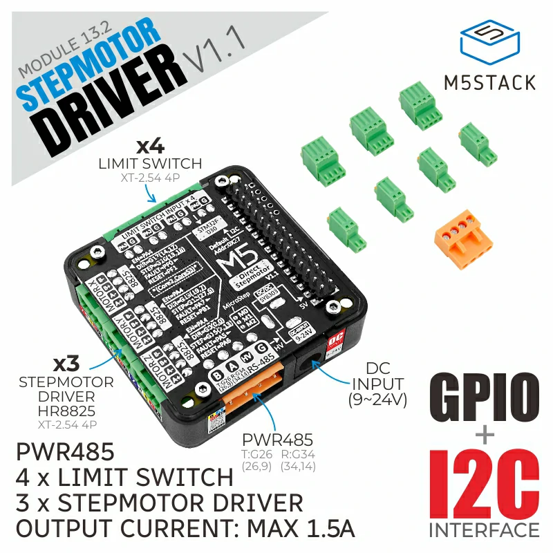
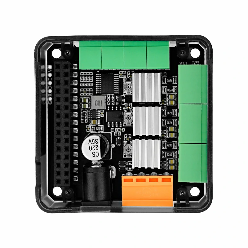
Stepmotor Driver Module 13.2 V1.1 is a stepper motor driver adapted to M5 main control, using STM32+HR8825 stepper motor drive scheme, providing 3-way bipolar stepper motor control interface. After stacking the driver with the M5 main controller, the ESP32 internal signal of the main control directly connects to the driver chip, which can realize independent control or multi-axis motor linkage. The module integrates STM32F030F4P6 chip as IO expansion, provides 4 sets of input signal terminals, 1 set of driver chip enable control, through I2C communication, can control and monitor the reset and status of the driver chip, can be used for external limit switch, motor brake function. The module contains 3 pads to control the 'subdivision mode of 3 sets of stepper motors to realize the subdivision adjustment of stepper motors. The integrated PWR485 communication interface (RS485 + 9-24V power input) and DC-JACK can be used for communication and the power supply mode will be more flexible. Support UIFlow graphical programming, the signal output can be easily configured, and the stepper motor can be controlled more precisely. This module is suitable for a variety of stepper motor motion control scenarios, such as printers, robotic arms, etc.
**Note: **
It is forbidden to plug and unplug the motor with electricity when using, and all operations should be carried out after the equipment is powered off to avoid damaging the module.
Features
- STM32F030F4P6@: ARM® 32-bit Cortex™-M0 CPU
- Triaxial HR8825 stepper motor driver
- Suitable for bipolar stepper motors
- Each channel has a current regulation potentiometer and can drive up to 1.5A
- Support multiple subdivision modes, up to 1/32 STEP subdivision
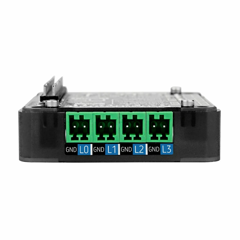
- 4 sets of signal input interface
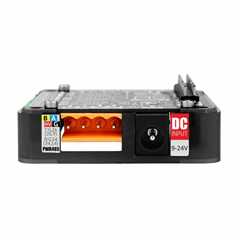
- PWR485 communication interface (RS485 + 9-24V power input)
- DC-JACK terminal input (9-24V)
- Development platform: Arduino, UIFlow
Includes
- 1x StepMotor Driver v1.1
- 4x 2.54-2P terminals
- 3x 2.54-4P terminals
- 1x 3.96-4P terminals
Applications
- 3D printer
- scanner
- CNC engraving machine control
- Motion module control
Specification
| Resources | Parameters |
|---|---|
| IO expansion chip | STM32F030F4P6 |
| Stepper motor drive chip | HR8825 |
| Support for segmentation mode | FULL、1/2、1/4、1/8、1/16、1/32 |
| Maximum drive current for a single channel | 1.5A |
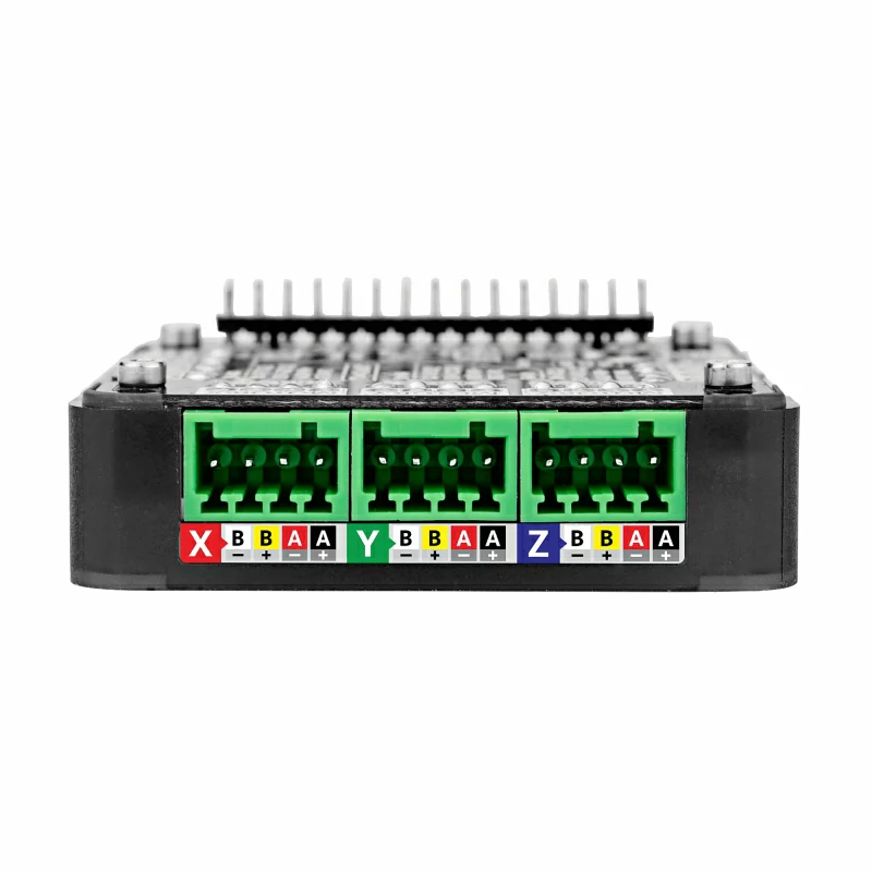
| Input signal terminal specifications | 2.54-2P |
| Motor terminal specifications | 2.54-4P |
| RS485 terminal block specifications | 3.96-4P |
| Operating temperature | 0-40°C |
| Product Size | 54.2 * 54.2 * 13.2mm |
| Package Size | 95 * 65 * 25mm |
| Product Weight | 40g |
| Package Weight | 60g |
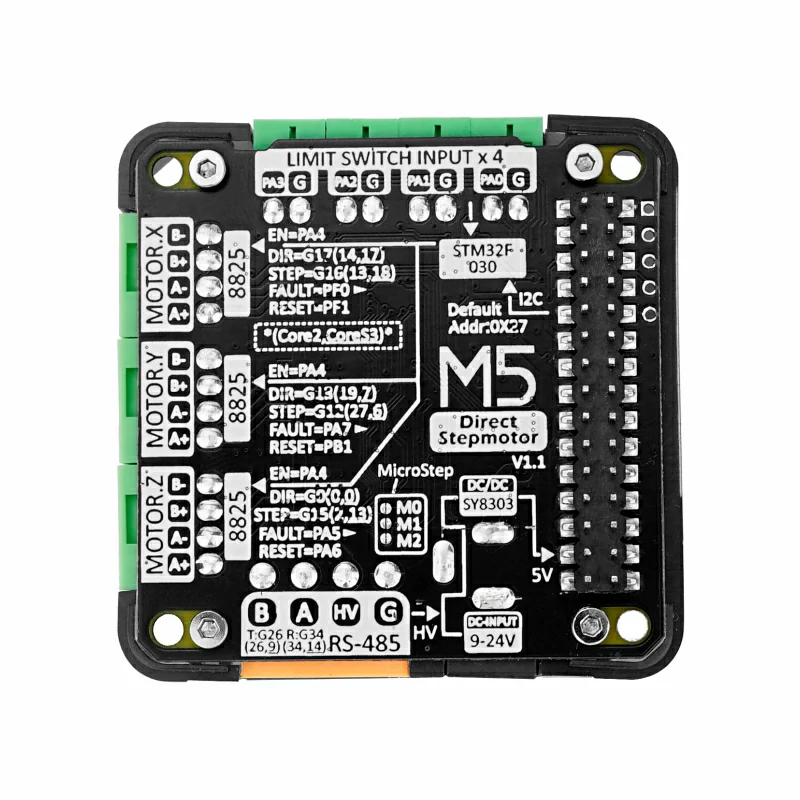
Micro step truth table
| M2 | M1 | M0 | Resolution |
|---|---|---|---|
| 0 | 0 | 0 | FULL |
| 0 | 0 | 1 | 1/2 |
| 0 | 1 | 0 | 1/4 |
| 0 | 1 | 1 | 1/8 |
| 1 | 0 | 0 | 1/16 |
| 1 | 0 | 1 | 1/32 |
| 1 | 1 | 0 | 1/32 |
| 1 | 1 | 1 | 1/32 |
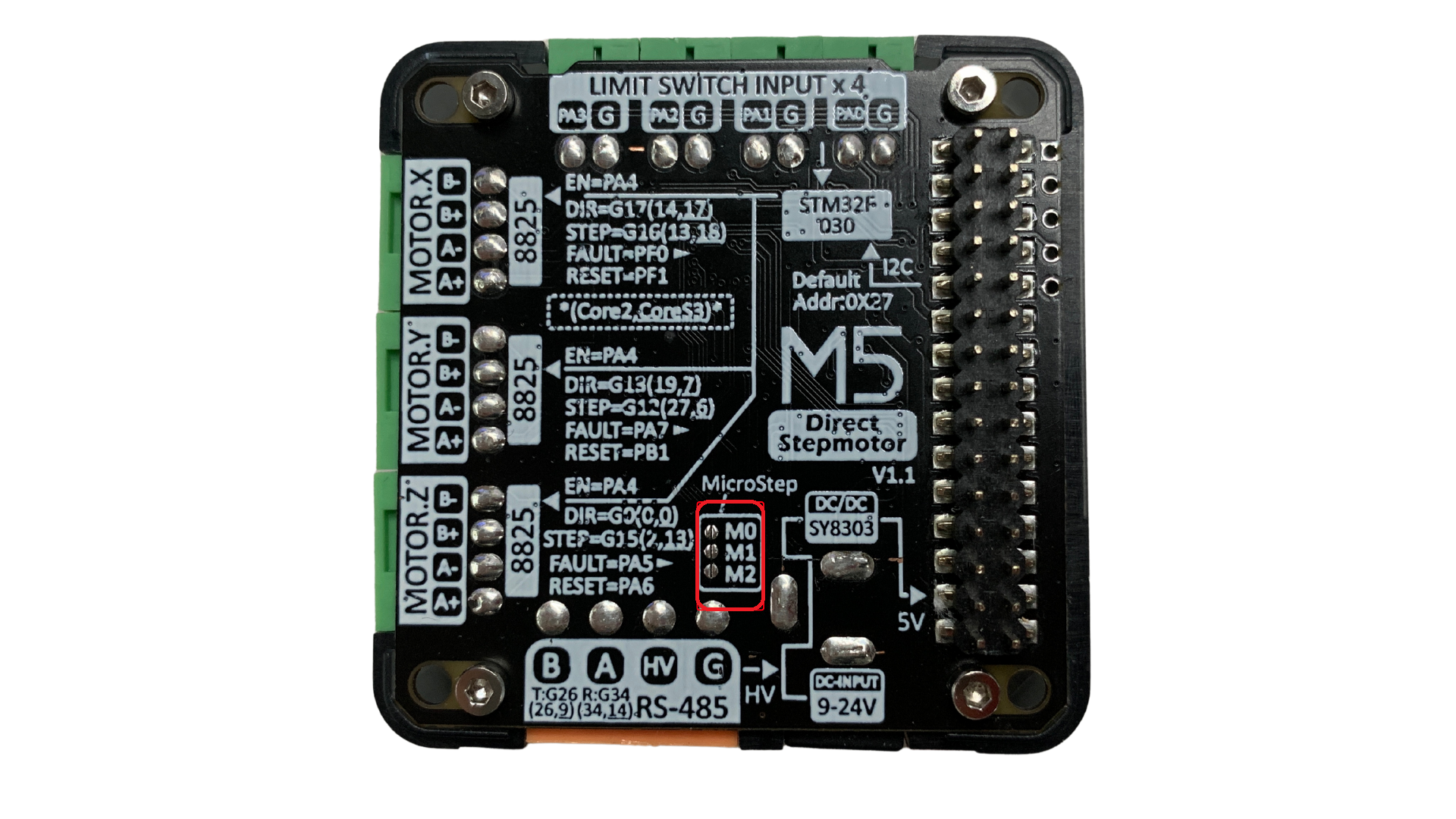
Adjusting the subdivision mode troubles the connection with the soldering iron soldering the associated pads.
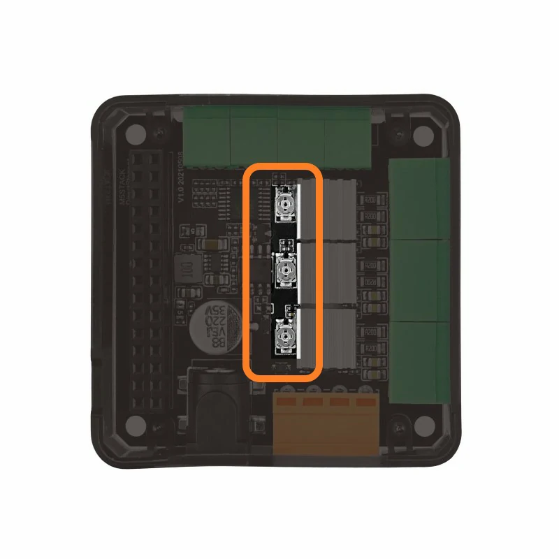
Drive current adjustment
The stepping motor has different specifications, and the required drive current may also be different. The current output can be adjusted through the metal knob on the module during use. In order to prevent the motor from overheating or damage, adjust the knob slowly during adjustment, observe the motor status or connect an ammeter to determine the appropriate drive current.
Related Link
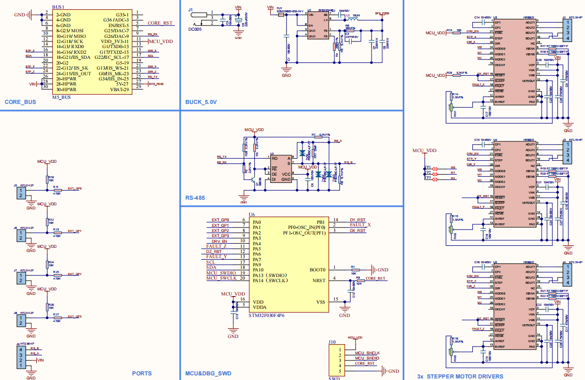
Schematic
Similar products comparison
| Features | GRBL 13.2 MODULE | STEPMOTOR DRIVER | STEPMOTOR DRIVER V1.1 |
|---|---|---|---|
| Control method | I2C communication | Pulse signal | Pulse signal |
| Firmware program | Onboard STM32, built-in GRBL firmware | No firmware, can be driven by ESP32 direct signal | Board STM32 with built-in firmware |
| Number of modules that can be stacked | 2 | 1 | 1 |
| Driver IC | DRV8825 | HR8825 | HR8825 |
| Subdivision adjustment | DIP switch | TCA9554 chip control | STM32 chip control |
| Interface | 3 groups of limit switch interfaces | 4 groups of custom signal input interfaces + RS485 communication interface | 4 groups of custom signal input interfaces + RS485 communication interface |
Examples
Arduino
UIFlow
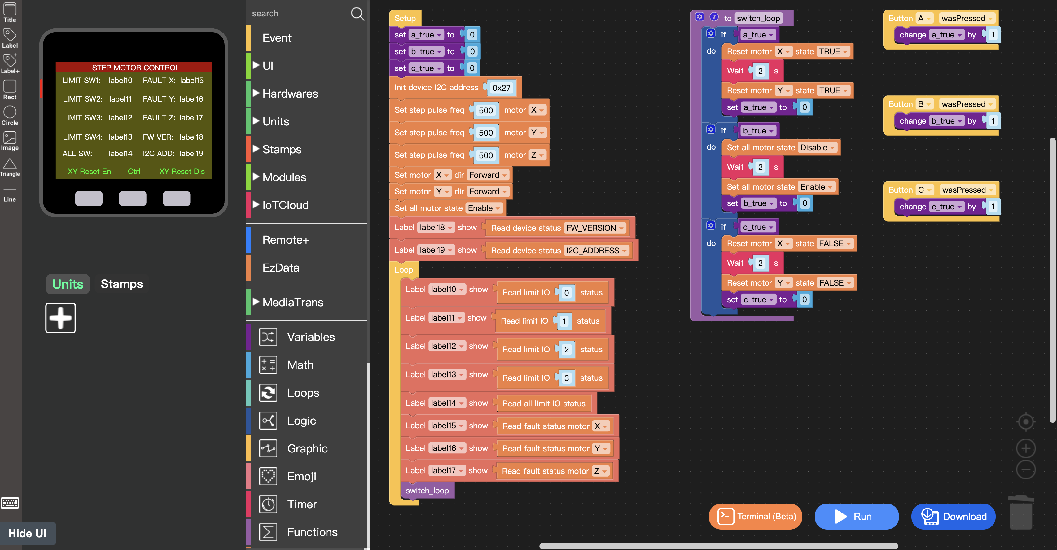
UIFlow Blocks
- Init device I2C address

- Set step pulse frequency

- Set micro step

- Set motor direction

- Set all motor state

- Set single motor state

- Reset motor state

- Set device I2C address

- Read all limit IO status

- Read limit IO status

- Read fault status

- Read device status

- Modbus Init

- Modbus Master write single coil

- Modbus Master write single register

- Modbus Master write multiple coils

- Modbus Master write multiple register

- Modbus Slave Init

- Modbus Slave update function

- Modbus Slave Send ADU response buffer

- Modbus Slave receive ADU request

- Modbus Slave get funtion code

- Modbus Slave Function code

- Modbus Slave get address

- Modbus Slave get quantity

- Uart write string

- Uart write a line

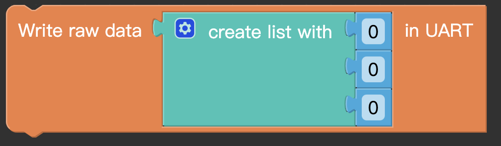
- Uart write raw data
- Uart read all

- Uart read characters

- Uart read line

- Uart remain cache